A driveshaft can look simple from the outside: two joints, a tube, a sliding section and end connections. In service, however, it is a rotating system in which every component must match the torque, speed, angle, operating length, environment and interfaces of the machine. A shaft that bolts into place is not necessarily a shaft that is safe, durable or suitable for the required balance quality.
JAZARION brings the selection and ordering process into one controlled project flow. The customer can start with an OE or part number, a VIN, an existing drawing, measured dimensions, a failed sample or only the operating data. The platform then connects catalog search, a guided technical brief, the Driveshaft AI Engineer, engineering review, documentation, qualified manufacturing and logistics.
The aim is broad application coverage: passenger and commercial vehicles, buses, agricultural equipment, construction and mining machines, industrial drives, marine and offshore equipment, energy assets, special machinery, prototypes and repeat-production programs. “Any driveshaft” does not mean that an automatic result is instantly approved for every duty. It means that different starting points and shaft architectures can enter the same disciplined route until the correct technical basis is confirmed.
Four ways to start a driveshaft project
The JAZARION driveshaft selection and ordering tool supports four practical scenarios.
- Known replacement: search by OE number, VIN, manufacturer, model, machine, drawing or shaft number.
- Measured replacement: enter compressed, operating and extended lengths; tube size; flange pilot and PCD; bolt pattern; spline information; photos and sample-inspection data.
- New or modified design: define torque, speed, angle, duty cycle, packaging envelope, service environment and target life for engineering selection.
- Components only: request compatible universal joints, yokes, flanges, companion flanges, tubes, splines, slip assemblies, centre supports, guards, fasteners or service parts.
These routes reduce the risk of treating one isolated dimension as a complete specification. An OE reference may identify a family but not a current revision. A sample may reveal geometry but not the original duty assumptions. A drawing may describe dimensions but omit shock loads, corrosion exposure or balancing requirements. The project record keeps those gaps visible.
What the Driveshaft AI Engineer does
The JAZARION Driveshaft AI Engineer turns operating inputs into a traceable preliminary engineering envelope. It can help organize the selection of:
- joint series and compatible yoke family;
- tube outside diameter, wall and material model;
- spline basis and required sliding travel;
- flange geometry, pilot, PCD, bolt pattern and end orientation;
- torque and fatigue reference margins;
- elastic twist and critical-speed screening;
- balancing and verification activities;
- open interfaces that still require measurements or engineering decisions.
The browser model provides a parametric 3D preview so the user can review proportions, end arrangements and packaging. It is useful for discussion and early coordination, but it is not a released manufacturing model. Exact components, proprietary tooth forms, production holes, weld details, tolerances and final material specifications remain subject to verified interfaces and engineering approval.
Automatic selection is a preliminary calculation, not a production release. The approved shaft, production CAD and final product passport require confirmed loads, dimensions, interfaces, applicable standards and an authorized engineering decision.
Select components as one compatible assembly
A reliable driveshaft is not built by choosing the “strongest” part from each catalog. Joint series, yokes, tube, spline, flange, weld arrangement, fasteners and balancing method must work together.
- Universal joints and yokes must match the torque regime, angle, lubrication strategy and service cycle.
- Tube and weld yokes must provide the required torsional capacity while maintaining critical-speed margin and manufacturable weld geometry.
- Splined slip assemblies must support required travel, contact pressure, sealing and lubrication without bottoming or separating.
- Flanges and companion flanges require confirmed pilot, PCD, hole pattern, face geometry, orientation and fastener requirements.
- Centre supports and multi-section layouts must be reviewed as a system, including bearing position, phasing and installation geometry.
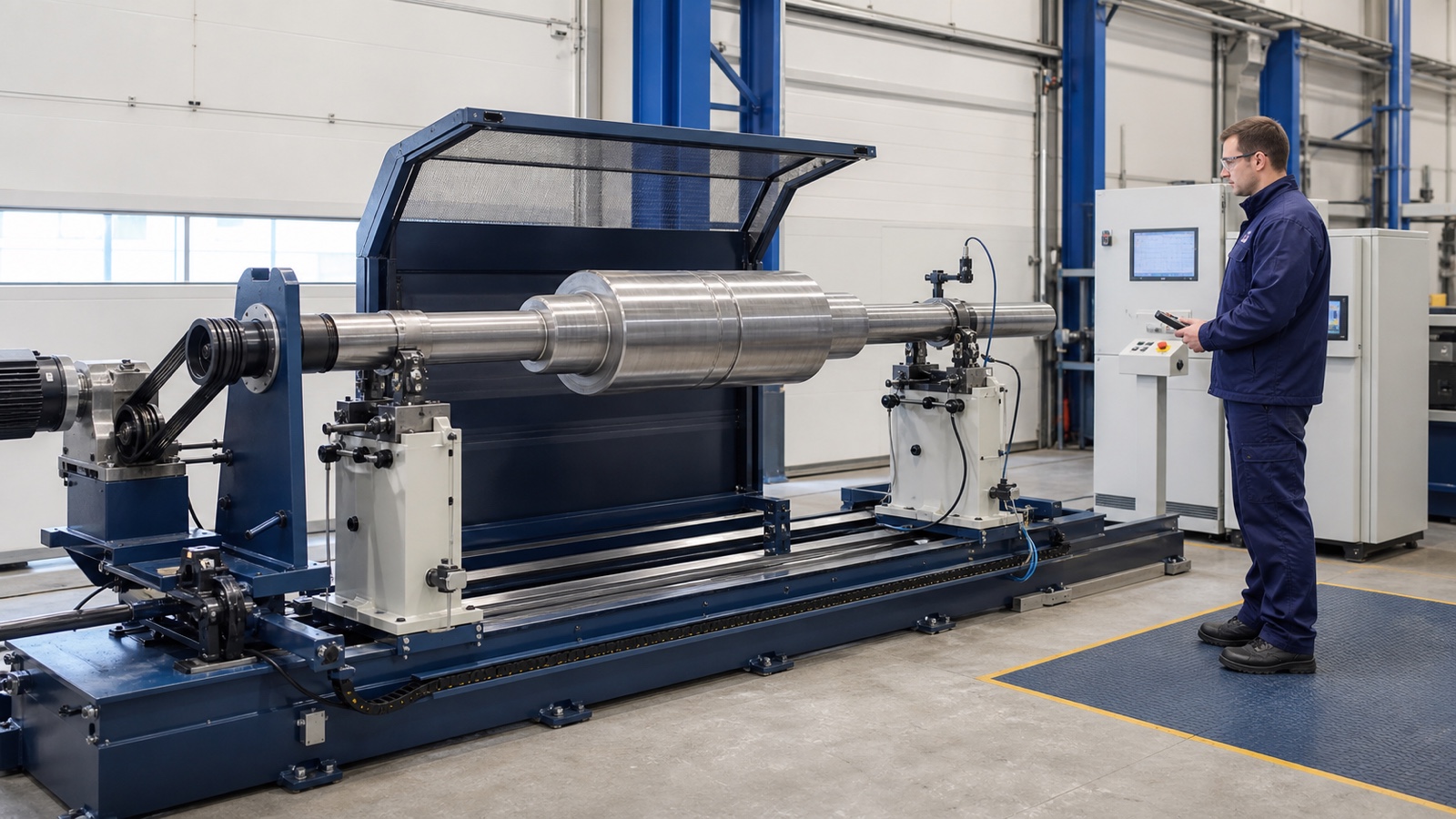
- Balancing requirements must reflect shaft behaviour, operating speed, correction planes and the agreed acceptance procedure.
For example, ISO 21940-11:2016 addresses procedures and tolerances for rotors with rigid behaviour. It is not a universal certificate for a driveshaft or its manufacturer. The applicable edition, product behaviour, OEM requirements, test speed, correction method and acceptance authority still need to be defined for the project.
From one specification to controlled engineering documentation
Once the preliminary selection is calculated, the same revision can feed a coordinated documentation package. Depending on project scope and access, this may include:
- a preliminary 3D mesh and a request for a reviewed STEP model;
- a general-arrangement drawing and DXF geometry;
- calculation inputs, formulas, margins, warnings and validation tasks;
- a bill of materials for the shaft and selected components;
- inspection and balancing fields;
- a project JSON record for controlled data exchange;
- a draft digital product passport.
This technical and design documentation reduces repeated interpretation. The quotation, drawing, model, component list, inspection plan and passport can refer to the same project code and revision. If a dimension changes, the change should move through the connected package rather than remain hidden in an email or an unmarked file.
What the digital product passport records
The digital product passport is the lifecycle record of the delivered shaft. Its exact contents depend on the project, but the controlled structure can cover:
- product and project identifiers;
- approved technical characteristics and interfaces;
- material and component records supplied with the order;
- drawing, CAD and revision references;
- inspection and balancing results;
- release status and responsible signatures;
- manufacturer and applicable certification-scope evidence;
- shipment, installation and service milestones;
- maintenance, repair and repeat-order history.
A draft passport generated from preliminary inputs is not proof that manufacturing or inspection has taken place. Production evidence is added only as the relevant activities are completed and accepted.
How JAZARION works with certified driveshaft manufacturers
“Certified manufacturer” must be verified, not used as a generic marketing label. JAZARION can route a project to a manufacturer whose capabilities, equipment, quality system, geography and applicable certification scope fit the specific shaft and destination.
The review may include the manufacturer’s current quality-management certificate, issuing body, validity, site and scope; welding and inspection capability where relevant; balancing equipment; traceability; process controls; and the ability to produce the required components and records. ISO 9001:2015 defines requirements for a quality management system, but a quality-system certificate alone does not prove technical capability for every driveshaft. Project-specific qualification remains necessary.
The selected manufacturer, accepted scope, required tests, exclusions and documentation are recorded in the quotation and, where included, the final product passport. JAZARION does not imply that every listed reference company is a partner, distributor or approved source for every project.
Worldwide logistics connected to the order
A global order is not complete when the shaft leaves the factory. Packaging, preservation, export documents, transport mode, customs requirements, insurance, tracking and delivery responsibility must match the product and destination.
JAZARION can keep available logistics milestones connected to the same project record used for engineering and production. The route may support a replacement shaft, a component shipment, a prototype, a recurring batch or an OEM program. Final cost, lead time, Incoterms, customs documents and destination availability are confirmed before order release; they are not guaranteed by submitting the initial brief.
What to prepare for a faster engineering review
Provide as much as you know, and mark uncertain data rather than estimating it as fact:
- vehicle, machine, vessel or industrial asset identification;
- OE, VIN, serial, drawing or previous shaft number;
- compressed, operating and extended lengths;
- torque, power, speed, angle, duty cycle and shock conditions;
- both end connections, flange pilot, PCD, holes and spline data;
- tube dimensions and available installation envelope;
- environment, temperature, corrosion, dust and maintenance conditions;
- photos, sample measurements, CAD files and failure observations;
- required standards, inspection, balancing and acceptance records;
- quantity, repeat demand, destination and requested delivery scope.
If the information is incomplete, start with the guided brief. If the geometry and duty still need to be developed, use the AI Engineer. If the application is already known, begin with the catalog search. All three paths can lead into the same engineering review and order process.
Start the project
Use JAZARION to search or configure a driveshaft, open the Driveshaft AI Engineer, or submit a protected manufacturing request. The result is not just a part number: it is a controlled route from application data to compatible components, reviewed documentation, qualified manufacturing, digital product history and worldwide delivery.