Short answer: for a rotor with rigid behaviour, the permissible residual unbalance is derived from the specified balance quality grade G, the rotor's maximum service speed and its mass. First calculate the permissible specific residual unbalance, e_per = 9549 × G / n. Then calculate the permissible residual unbalance, U_per = e_per × M. With G in mm/s, n in r/min and M in kg, the results are e_per in µm and U_per in g·mm. The total tolerance must then be allocated to the relevant tolerance planes; it must not automatically be divided equally between two planes.
This guide explains the calculation and the engineering decisions around it. It is not a substitute for the applicable rotor specification, contract, current standard, risk assessment or qualified engineering approval.
What ISO 21940-11 covers
ISO 21940-11:2016 establishes procedures and unbalance tolerances for rotors with rigid behaviour. Its stated scope includes the magnitude of permissible residual unbalance, the required number of correction planes, allocation to tolerance planes and accounting for balancing-process errors. The official ISO record also lists Amendment 1:2022.
The phrase “rigid behaviour” matters. It does not mean that the rotor is physically impossible to bend. It means that, within the relevant balancing-speed range, its unbalance can be corrected satisfactorily without having to account for significant elastic deformation modes. Rotors with flexible behaviour require a different engineering route; ISO 21940-12:2016 addresses those procedures and criteria.
The standard is not a catalog that assigns one universal grade to every product. The grade and acceptance requirements may come from a product standard, an OEM drawing, a customer specification, operating experience or a justified engineering assessment. When a contract names an ISO edition, use that edition and its applicable amendments rather than silently substituting another document.
Four quantities that must not be confused
Unbalance amount U
Unbalance amount is the product of an unbalance mass and its radial distance from the shaft axis:
U = m_u × r
If m_u is in grams and r is in millimetres, U is in g·mm. Unbalance is a vector: its amount without its angle is not a complete correction instruction.
Specific residual unbalance e
Specific residual unbalance relates residual unbalance to rotor mass:
e = U / M
It can be understood as the residual eccentricity of the rotor's mass centre. When U is in g·mm and rotor mass M is in kg, the numerical result for e is in µm.
Balance quality grade G
The balance quality grade connects permissible specific residual unbalance with angular speed:
G = e_per × ω
Here G is expressed in mm/s, e_per in mm and ω in rad/s. A lower G value represents a tighter balance-quality requirement at the same speed and mass. It does not mean that the balancing machine itself has that “accuracy class.”
Correction mass
The correction mass depends on the available correction radius:
m_c = U / r_c
For example, 240 g·mm can be represented by 3 g at an 80 mm radius. The same unbalance can be represented by many mass-radius combinations. The permitted drilling depth, weld-on weight, clip, screw or material-removal geometry is a separate manufacturing decision.
The calculation, step by step
Step 1: establish the controlling requirement
Before selecting a grade, check the drawing, product standard, customer specification and acceptance plan. Record the applicable edition, rotor configuration, mass basis, service-speed definition and whether the stated tolerance is total or per plane.
Step 2: use maximum service speed
For the grade calculation, n is normally the maximum service speed relevant to the specified balance requirement—not simply the balancing-machine speed. A rotor may be balanced at a lower speed while its tolerance is derived from a higher service speed. If the governing specification defines another reference speed, follow that specification and record it.
Step 3: calculate angular speed
ω = 2πn / 60
where n is in r/min.
Step 4: calculate permissible specific residual unbalance
e_per = G / ω
For practical units:
e_per [µm] = 9549 × G [mm/s] / n [r/min]
The constant is a unit conversion derived from 60 × 1000 / 2π, rounded for engineering use.
Step 5: calculate total permissible residual unbalance
U_per [g·mm] = e_per [µm] × M [kg]
This is the permissible residual-unbalance amount for the rotor before allocation to the tolerance planes.
Step 6: allocate the tolerance to the planes
For a two-plane rotor, do not assume that each plane receives U_per / 2. Allocation depends on rotor geometry, mass distribution, bearing or support locations and the selected tolerance planes. A symmetric rotor may sometimes produce a near-equal allocation, but symmetry must be demonstrated rather than presumed.
Step 7: define the acceptance method
State how residual unbalance will be verified, which setup and tooling will be used, how repeat runs are handled and how measurement and assembly errors are considered. ISO 21940-14:2012, with its listed amendment and ongoing revision status at the time of this review, addresses assessment of balance errors. Confirm its current status before putting it into a new contract.
Quick reference table: permissible specific residual unbalance
The values below are calculated from e_per = 9549 × G / n. They are an engineering ready reckoner, not a reproduction of a standards table.
| Grade G | 750 r/min | 1,500 r/min | 3,000 r/min | 6,000 r/min | 12,000 r/min |
|---|---|---|---|---|---|
| G 16 | 203.7 µm | 101.9 µm | 50.9 µm | 25.5 µm | 12.7 µm |
| G 6.3 | 80.2 µm | 40.1 µm | 20.1 µm | 10.0 µm | 5.0 µm |
| G 2.5 | 31.8 µm | 15.9 µm | 8.0 µm | 4.0 µm | 2.0 µm |
| G 1 | 12.7 µm | 6.4 µm | 3.2 µm | 1.6 µm | 0.8 µm |
| G 0.4 | 5.1 µm | 2.5 µm | 1.3 µm | 0.6 µm | 0.3 µm |
To convert a table value to total permissible residual unbalance, multiply it by rotor mass in kilograms. To estimate an equivalent correction mass at a chosen radius, divide the resulting g·mm value by that radius in millimetres.
Worked example 1: industrial fan impeller
Assume the approved requirement is G 6.3, rotor mass is 80 kg and maximum service speed is 1,500 r/min.
e_per = 9549 × 6.3 / 1500 = 40.1 µmU_per = 40.1 × 80 = 3208.5 g·mm- At a 250 mm correction radius, the total vector-equivalent correction mass is
3208.5 / 250 = 12.83 g.
The 12.83 g figure is not an instruction to place that mass anywhere on the rotor. The measured angle, correction method and allocation between planes still determine the actual correction.
Worked example 2: compact high-speed rotor
Assume an approved G 2.5 requirement, rotor mass 4 kg and maximum service speed 9,000 r/min.
e_per = 9549 × 2.5 / 9000 = 2.65 µmU_per = 2.65 × 4 = 10.61 g·mm- At a 45 mm radius, the total vector-equivalent correction mass is
10.61 / 45 = 0.236 g, or about 236 mg.
At this scale, tooling repeatability, shaft and adapter runout, key convention, cleanliness and the resolution of the correction method can consume a meaningful portion of the tolerance. A mathematically correct number is not yet proof that the process can hold it.
Worked example 3: medium-speed impeller
Assume G 6.3, rotor mass 12 kg and maximum service speed 3,000 r/min.
e_per = 9549 × 6.3 / 3000 = 20.05 µmU_per = 20.05 × 12 = 240.6 g·mm- At an 80 mm radius, the total vector-equivalent mass is
240.6 / 80 = 3.01 g.
If the rotor needs two-plane balancing, the engineering drawing or allocation calculation must convert the total tolerance into limits for the two tolerance planes.
How to choose G 6.3, G 2.5, G 1 or another grade
Start with the product requirement, not a generic chart
A published application chart is useful for an initial discussion, but it is not the acceptance authority for a specific rotor. Hofmann's permissible residual-unbalance reference illustrates commonly associated rotor groups for grades such as G 6.3, G 2.5, G 1 and G 0.4. Treat these examples as orientation only.
Consider the complete assembly
Ask whether the rotor will operate with a key, coupling half, pulley, fan blades, seals, fasteners, liquid contents or replaceable tooling. Balancing a component in one configuration and installing it in another can create an assembly-state error larger than the intended tolerance.
Consider speed range and operating sensitivity
Because permissible eccentricity decreases as speed rises, copying a grade from a slower rotor can produce the wrong limit. Also consider bearing loads, vibration sensitivity, clearances, product quality, noise, fatigue risk and the consequences of failure.
Avoid “the lowest possible grade” as a purchasing strategy
A tighter grade is not automatically a better engineering decision. It can demand more stable tooling, better concentricity, smaller correction increments, more runs and more inspection time. Specify the grade needed by the application, then demonstrate that the process can achieve and verify it economically.
Grade G is not a balancing-machine accuracy specification
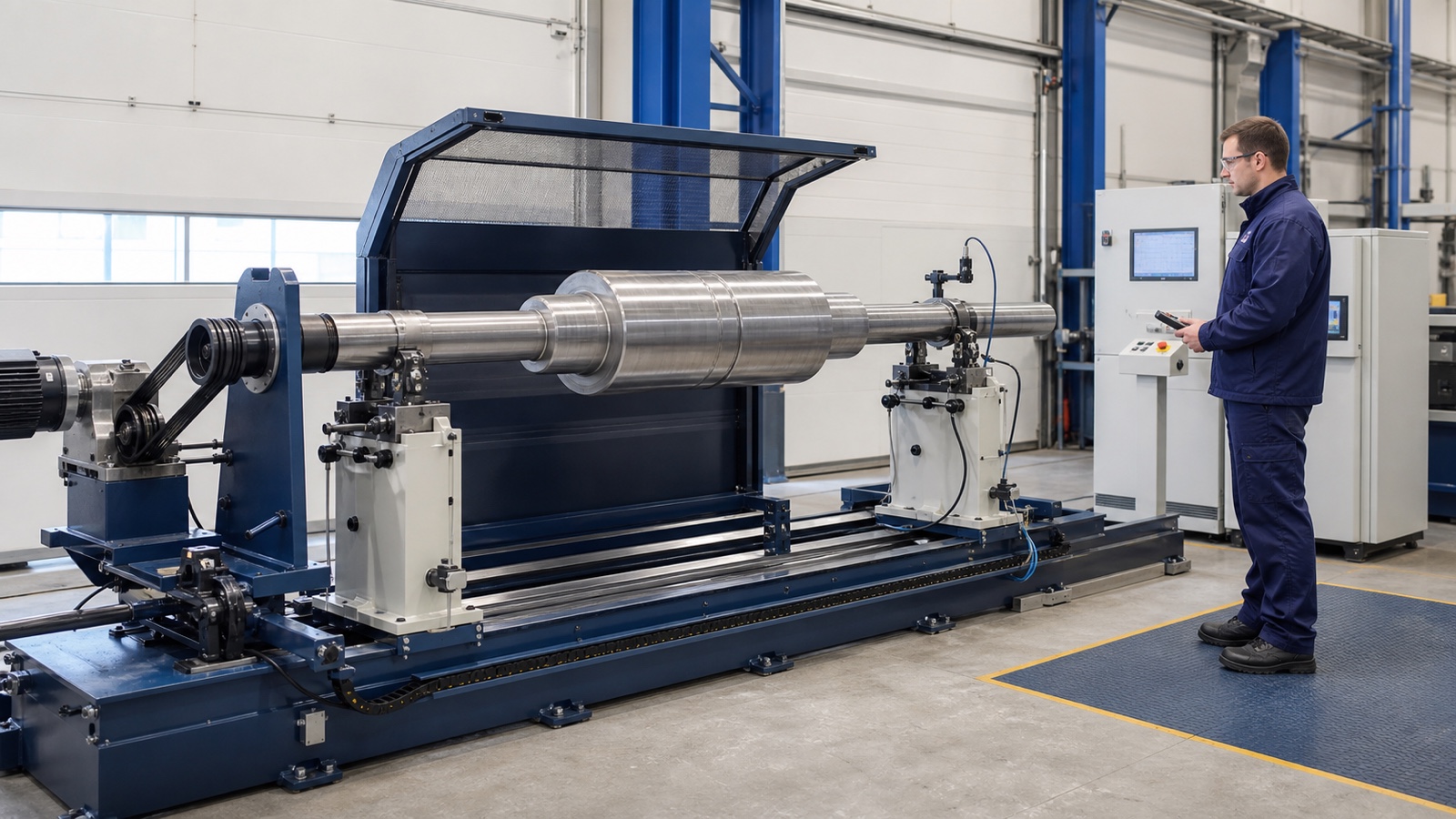
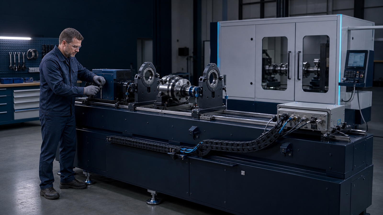
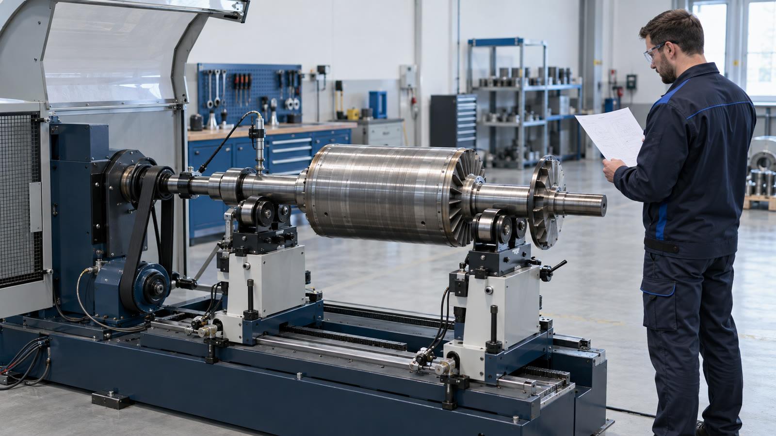
A rotor grade describes the allowable residual state of the rotor at a defined service speed. A balancing machine must be evaluated through its own capability: rotor range, measuring principle, minimum achievable residual unbalance, unbalance reduction performance, plane separation, tooling, calibration, repeatability and operating conditions.
ISO 21940-21:2022 covers the evaluation of hard-bearing and soft-bearing balancing machines. When selecting equipment, connect the rotor tolerance to a real acceptance test instead of relying on a brochure statement that the machine “supports G 2.5.”
Useful acceptance questions include:
- Can the machine demonstrate the required residual unbalance on the actual rotor family or a representative test rotor?
- Is the required limit comfortably above the machine-and-tooling measurement floor?
- Does the setup provide sufficient plane separation?
- Are adapters, drive components and journals repeatable after removal and refitting?
- Can the correction method produce increments smaller than the remaining tolerance budget?
- Does the report preserve rotor ID, setup, speed, units, angles, before/after values and acceptance limits?
Hofmann's current measuring-system description is a useful example of the distinction: the measurement system may calculate permissible residual unbalance and compare tolerance automatically, while machine configuration, calibration and the physical process still determine whether the result is valid.
Common calculation and specification errors
Using balancing speed instead of service speed
The rotor may be measured at one speed and specified at another. Record both values and their roles.
Confusing µm, g·mm and correction mass
Specific residual unbalance, total unbalance and correction mass are related but not interchangeable. Always write the unit next to the value.
Dividing total tolerance equally between two planes
Equal allocation is not a universal rule. Use rotor geometry and the applicable procedure.
Ignoring the angle
Unbalance is a vector. An amount without an angle cannot define a correction.
Selecting G from a familiar product name alone
Two fans or two motor rotors can have different mass, speed, geometry, bearing sensitivity and contractual requirements.
Treating a calculated limit as guaranteed capability
The calculation defines a target. Capability must be demonstrated with the actual measurement chain, tooling and correction process.
Demanding zero unbalance
Zero is not a realistic acceptance statement. Measurement resolution, material granularity, runout, assembly variation and process errors require a finite, verified tolerance.
Information to put on the drawing or RFQ
Provide enough context for the supplier to reproduce both the calculation and the acceptance:
- rotor name, drawing number and revision;
- mass and dimensional range;
- maximum service speed and balancing speed;
- required grade G or explicit per-plane tolerance;
- rigid- or flexible-behaviour assessment;
- complete balancing configuration and key convention;
- tolerance-plane and correction-plane locations;
- allowed correction methods, radii and material limits;
- initial-unbalance envelope if known;
- required report, traceability and repeatability test;
- safety, guarding and overspeed requirements where applicable;
- controlling standard, edition, amendment and customer exceptions.
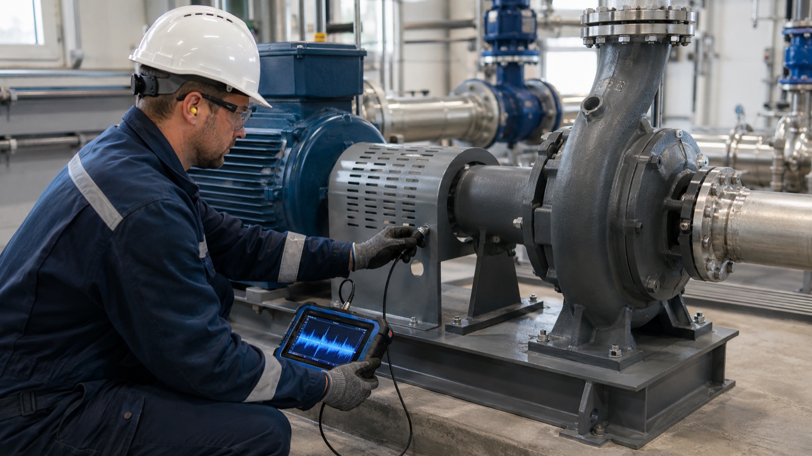
These inputs also determine whether a soft-bearing or hard-bearing balancing machine is the better architecture for the production task. If vibration is being investigated on an installed machine, first separate unbalance from other fault mechanisms using a disciplined vibration-diagnostics process.
Frequently asked questions
What is permissible residual unbalance?
It is the maximum residual unbalance amount accepted in a defined tolerance plane after balancing, under specified conditions. It must be stated with units and, where relevant, plane allocation and verification rules.
How do I calculate permissible residual unbalance?
For a rigid-behaviour rotor using grade G, calculate e_per [µm] = 9549 × G / n, then U_per [g·mm] = e_per × M. Confirm that the selected grade, speed, mass basis and plane allocation match the controlling specification.
Is G 2.5 always better than G 6.3?
No. G 2.5 is tighter at the same mass and speed, but “tighter” is not automatically “correct.” Use the requirement justified by the product, service conditions and governing document.
Does G 2.5 mean 2.5 g·mm?
No. G is a balance quality grade expressed in mm/s. The allowable g·mm value depends on rotor mass and service speed.
Is U_per a total value or a per-plane value?
The calculation first gives a total permissible residual-unbalance amount. For a rotor balanced in two planes, it must be allocated to tolerance planes using the applicable method; do not assume a 50/50 split.
Can a rotor be balanced to zero?
Not as a defensible production requirement. A finite tolerance and a repeatable verification method are required.
Can a trained operator perform the calculation?
A trained technician can apply an approved worksheet and measurement procedure. Selecting the grade, defining plane allocation, judging applicability and approving deviations require a competent specialist with authority under the company's engineering and quality system.
When does this calculation not apply directly?
It does not directly resolve flexible-rotor behaviour, resonant operating conditions, assembly-state changes or special product requirements. Those cases require the applicable rotor standard and a project-specific engineering assessment.
From tolerance to a verifiable balancing process
The useful output is not a grade alone. It is a controlled chain: requirement, rotor configuration, calculation, plane allocation, machine setup, correction method, repeatable measurement and traceable acceptance report.
JAZARION connects this engineering definition with balancing-machine architectures, a configurable balancing-machine builder and a global engineering-production network. To review a real rotor family, submit its mass, dimensions, speed range, drawing, target grade and production context through JAZARION engineering review.
Sources and review status
Technical records checked on 12 September 2026. Standards can be revised; verify the contractual edition before use.
- ISO 21940-11:2016 — procedures and tolerances for rotors with rigid behaviour
- ISO 21940-11:2016/Amd 1:2022
- ISO 21940-12:2016 — procedures and tolerances for rotors with flexible behaviour
- ISO 21940-14:2012 — procedures for assessing balance errors
- ISO 21940-21:2022 — description and evaluation of balancing machines
- Hofmann — permissible residual unbalance reference
- Hofmann — measuring systems for unbalance measurement and analysis