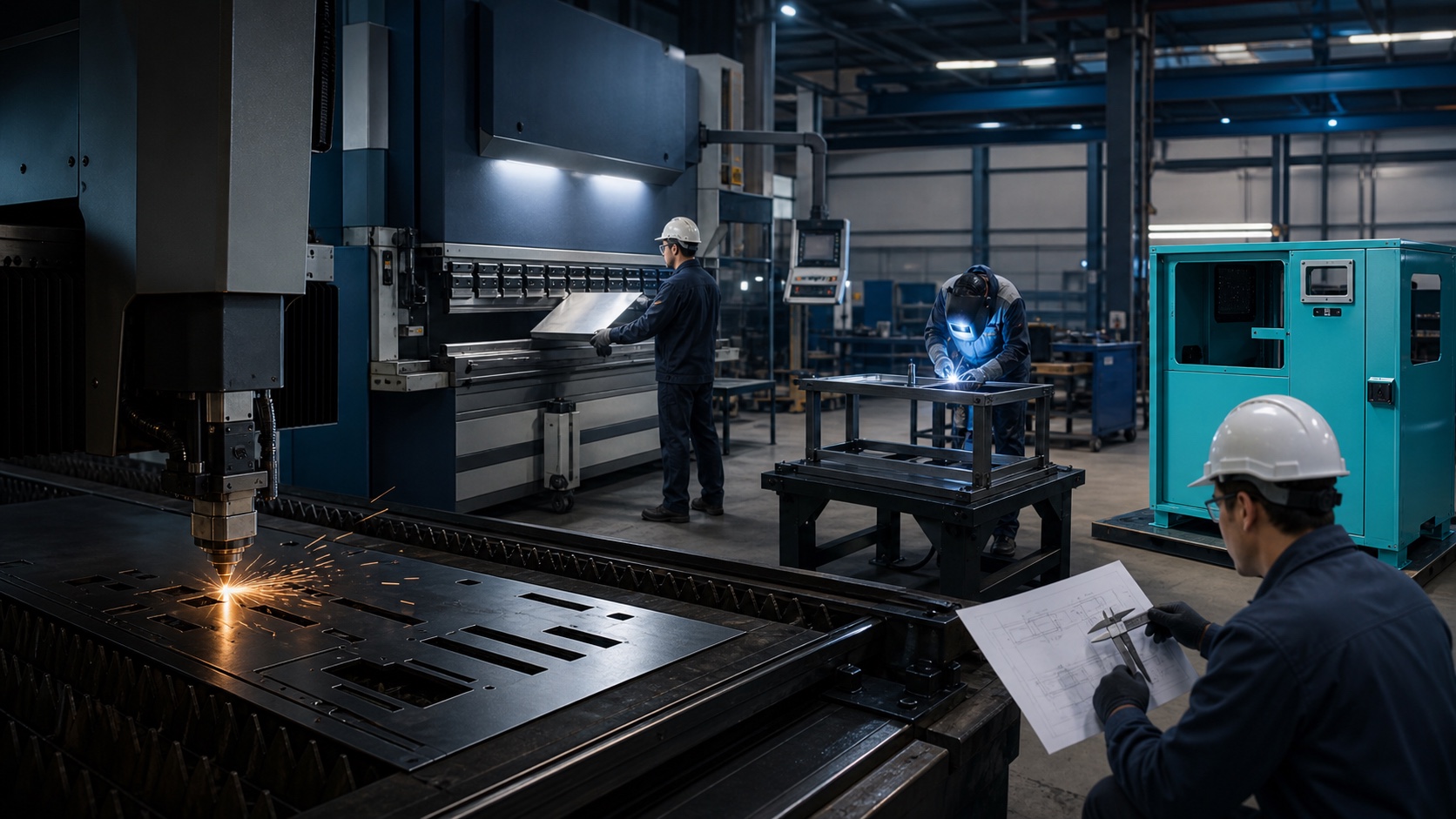
Metal fabrication is not a single operation. It is a controlled sequence that turns material, drawings and functional requirements into a finished component or assembly. Laser cutting may create the profile, but bend allowances determine whether the enclosure closes correctly. Welding may create the structure, but the joint sequence determines whether critical faces remain within tolerance. Powder coating may provide the final appearance, but its adhesion depends on the preparation completed before the part enters the booth.
For this reason, the most useful question is not “Which machine should cut this part?” It is: Which manufacturing route will deliver the required geometry, function, finish, documentation and landed result with controlled risk?
This guide explains how to compare laser, plasma and abrasive waterjet cutting; how to prepare sheet-metal parts for bending; how welding and fitting influence accuracy; and how abrasive blasting, laser cleaning and powder coating should be integrated into one production plan.
Start with the part, not the process
A technically useful request begins with the operating conditions and acceptance criteria. Before selecting a process, define as much of the following as possible:
- material grade, condition and required traceability;
- sheet or plate thickness and starting form;
- part quantity, expected repeat orders and batch strategy;
- 2D profile data and a controlled 3D model where applicable;
- critical dimensions, datums and realistic tolerances;
- edge, burr, heat-affected-zone and surface requirements;
- bend direction, inside radius and cosmetically sensitive faces;
- weld standard, inspection scope and distortion limits where required;
- preparation grade, surface profile, masking and coating system;
- destination, packing constraints and required project records.
When these inputs are incomplete, process selection becomes guesswork. A supplier may still quote, but the quotation can contain assumptions that later affect price, lead time or acceptance. A controlled request makes those assumptions visible before production release.
Laser, plasma or waterjet: a practical comparison
No cutting process is universally “best.” Material, thickness, profile complexity, edge condition, heat sensitivity, quantity and downstream operations must be assessed together.
- Laser cutting
- Strong fit: detailed profiles, small features, repeatable sheet work and efficient nesting.
- Watch points: heat input, assist-gas choice, reflective alloys, pierce condition and edge oxide.
- Downstream question: will the edge be welded, bent, coated, machined or left visible?
- Plasma cutting
- Strong fit: productive cutting of electrically conductive plate, robust structural profiles and larger features.
- Watch points: wider kerf, heat-affected zone, angularity, dross and possible finishing allowance.
- Downstream question: is the cut edge an as-cut feature or a preparation for welding or machining?
- Abrasive waterjet cutting
- Strong fit: cold cutting, heat-sensitive material, mixed material families and thick or laminated stock.
- Watch points: taper, abrasive condition, entry marks, cutting speed, moisture and consumable cost.
- Downstream question: which face is controlled, and is secondary machining needed for precision interfaces?
Laser cutting: precision depends on the entire setup
Laser cutting is often selected for detailed sheet-metal profiles, repeatable batches and parts that proceed directly to bending. However, the word “laser” does not define the delivered quality by itself. Source type, power, focus, nozzle condition, assist gas, material surface, nesting, piercing strategy and machine condition all affect the edge.
For fabrication drawings, identify which edges are functional, cosmetic or intended for welding. Small holes, narrow webs and features close to bend lines require particular attention. If an oxide-free edge is needed for a later coating or welding operation, this should be discussed before cutting rather than discovered during finishing.
Thermal-cut quality can be specified through agreed drawing or delivery requirements. ISO 9013, for example, provides a framework for classifying geometric product specifications and quality tolerances for thermal cuts, including laser and plasma cutting. The applicable class and inspection method still need to be agreed for the actual project.
Plasma cutting: productive when the edge requirement is defined correctly
Plasma cutting is a practical route for electrically conductive plate and many structural applications. It can be the right economic choice when the geometry, material and required edge condition do not justify a finer cutting route.
The quotation should state whether dross removal, edge dressing, bevel preparation or machining allowance is included. Hole quality, cut angularity and heat input should be reviewed against the function of the feature. A plasma-cut hole intended only for clearance is a different requirement from a bore that locates a bearing or precision pin.
Abrasive waterjet cutting: a cold process with its own geometry controls
Waterjet cutting avoids a thermal heat-affected zone, which makes it valuable for heat-sensitive materials, certain alloys, composite stacks and cases where thermal transformation is unacceptable. That advantage does not remove the need for process control.
The project should define the controlled face, acceptable taper, entry and exit conditions, edge striation and any allowance for final machining. Abrasive selection, cutting speed and nozzle condition influence both cost and edge quality. Parts should also be cleaned and dried appropriately before subsequent inspection, bonding, welding or coating.
Sheet-metal bending: the flat pattern is an engineering output
A cut blank becomes a functional sheet-metal part only when the bend route is feasible and the developed length is correct. The model must account for inside bend radius, material thickness, tooling, grain direction, bend allowance or deduction, and springback.
Features near a bend can stretch or distort. Holes, slots, louvers, formed details and short flanges should be checked against the selected tooling. Reliefs may be required at corners. The sequence must also allow the part to enter and leave the press brake without colliding with the punch, die, backgauge or previously formed flanges.
For repeat orders, do not treat the flat pattern as an uncontrolled export. Keep the approved model, drawing revision, material definition, bend table and inspection method connected to the part record. If the manufacturer develops the flat pattern, the responsibility for approving it should be explicit.
A useful bending checklist
- Mark critical finished dimensions from agreed datums, not only dimensions on the flat.
- Identify the required inside radius when it is functionally important.
- State whether visible grain, rolling direction or brushed finish must follow a direction.
- Keep holes and cut-outs away from bend influence zones, or approve expected deformation.
- Define cosmetic faces and acceptable tooling marks.
- Confirm how coating thickness will affect fitted interfaces, threads and grounding points.
Welding and fitting: control distortion before it reaches inspection
Welding joins parts, but it also introduces heat, shrinkage and residual stress. A fabrication can contain individually correct components and still fail assembly because the weld sequence pulled datums out of position.
Good preparation begins with joint design, access, fit-up gaps, edge preparation, fixture strategy and a realistic inspection plan. Tack welds, welding sequence and balanced heat input can help manage movement. Critical faces may need machining after welding rather than an unrealistic as-welded tolerance.
The production scope should distinguish among cutting, fitting, welding, dressing, straightening, machining and inspection. It should also define whether welds remain as deposited, are blended for a cosmetic surface or require a particular profile. Over-finishing can be as problematic as under-finishing when it removes useful weld material or changes the intended geometry.
Where a project requires a specific welding code, procedure qualification, welder qualification, inspection method or record package, those requirements must be named in the technical and commercial scope before production. They should not be assumed from a marketing description of “high-quality welding.”
Surface preparation: combine sandblasting and shot blasting into one controlled scope
Sandblasting and shot blasting belong in one decision area: abrasive blasting and surface preparation. The practical objective is to remove contamination, corrosion products, scale or previous coatings and, when needed, create a surface profile suitable for the next process.
The labels are often used inconsistently across markets. In many workshops, “sandblasting” is used as a broad name for air-propelled abrasive blasting even when the selected media is not sand. “Shot blasting” often refers to equipment that mechanically propels metallic or other media. The correct choice depends on the substrate, component geometry, contamination, required cleanliness, surface profile, recovery system and environmental controls—not on the label alone.
A useful abrasive-blasting specification identifies:
- substrate and initial surface condition;
- areas to clean, protect or mask;
- required preparation grade and reference method;
- required surface profile or comparator where relevant;
- approved abrasive family and contamination controls;
- maximum interval and storage conditions before coating;
- dust removal and inspection method;
- treatment of edges, welds, recesses and inaccessible areas.
ISO 8501-1 is widely used for visual assessment of steel-surface cleanliness, while the ISO 8503 series addresses roughness characteristics of blast-cleaned steel. The project must state the applicable edition, required grade and verification method rather than writing only “blast clean.”
Laser cleaning: targeted removal without abrasive media
Laser cleaning can remove selected oxides, residues or coatings by controlled energy delivery. It is useful where the process must be localized, where abrasive media is undesirable, or where a component cannot easily be placed in a blasting system.
It is not a universal substitute for every preparation method. Material response, coating type, layer thickness, geometry, focus, scan speed, heat input, extraction and the required final profile all matter. A sample or qualified parameter window may be necessary before treating a valuable or safety-critical component.
The acceptance criterion should describe the result—not only the equipment: which layer must be removed, which substrate changes are unacceptable, what area is treated, and how cleanliness will be verified.
Powder coating: the finish begins before the powder is applied
Powder coating can provide a durable, repeatable finish for enclosures, frames, brackets and many industrial components. Colour and gloss are only part of the specification. Surface preparation, pretreatment, coating chemistry, film build, curing, grounding and part geometry determine the delivered performance.
The request should identify:
- substrate and service environment;
- colour reference, gloss and permitted visual variation;
- coating family where performance requires it;
- target film-thickness range and measurement approach;
- pretreatment and preparation requirements;
- masked faces, threads, bores, electrical contacts and bonding points;
- hanging points and acceptable rack marks;
- cure verification and required adhesion or performance testing;
- packing method that protects the finished surface.
Threads and close fits require deliberate masking or post-process allowance. Drainage and venting must be considered for closed or partially closed fabrications. Weld spatter, sharp edges, oil and silicone contamination should be resolved before coating, not hidden beneath it.
Build one quality plan across all operations
When cutting, bending, welding and finishing are quoted as unrelated services, interface risk can fall between suppliers. An integrated quality plan keeps the acceptance logic connected from the first blank to the packed assembly.
At minimum, define:
- the controlled drawing and model revision;
- incoming material evidence and substitution rules;
- first-article or setup approval where the risk justifies it;
- in-process checks after cutting, forming and welding;
- dimensional inspection after operations that can move the part;
- surface-preparation and coating records required by the project;
- final visual, dimensional and functional acceptance;
- marking, preservation, packing and shipping requirements;
- the record package that travels with the order.
Inspection should focus on function and risk. Applying tight tolerances to every dimension can increase cost without improving performance. Critical-to-function features, assembly interfaces, sealing surfaces, datum relationships and safety-related characteristics deserve the clearest acceptance rules.
A production-ready request for quotation
For a faster and more comparable review, include:
- STEP or another agreed 3D format plus DXF/DWG or controlled 2D profiles where appropriate;
- a dimensioned PDF drawing with revision and units;
- material specification, thickness and acceptable substitutions;
- quantity, lot strategy and forecast context if repeat demand is expected;
- critical tolerances and inspection requirements;
- bend, weld and finish notes;
- colour, texture, masking and surface-preparation requirements;
- target destination and any packing constraints;
- required certificates, inspection reports and traceability records;
- photographs or an existing-part reference when reverse engineering is involved.
If the model is not complete, use the JAZARION Concept Studio to organise the design intent and missing engineering inputs. Existing component references can be attached from the industrial CAD library. Final manufacturability, process capability, price and lead time still require project-specific review.
Global sourcing without losing engineering control
Global production is not achieved by translating a drawing and sending it to the lowest bidder. Material designations, standard editions, coating systems, inspection language, export packing and available processes can vary by market.
Keep the engineering baseline independent of the supplier location: define the function, controlled files, applicable standards, accepted equivalents, evidence requirements and change-approval route. Then evaluate each manufacturing route against capacity, quality controls, documentation, logistics and destination requirements.
Automatic language selection can improve access, but the technical record must remain controlled. On multilingual projects, approved terminology, units, revision identifiers and numeric acceptance criteria should stay consistent across English, Arabic, Russian and any additional language used by the participants.
Frequently asked questions
Which is better for metal cutting: laser, plasma or waterjet?
The answer depends on material, thickness, geometry, edge condition, heat sensitivity, quantity and downstream work. Laser is often effective for detailed repeatable sheet profiles; plasma is productive for many conductive-plate applications; waterjet is valuable where a cold cutting process or broad material compatibility is required. The final choice should be based on the complete part route.
Does laser cutting eliminate the need for edge finishing?
Not always. Edge requirements depend on the material, cut parameters and next operation. Welding, coating, cosmetic exposure, fatigue-sensitive service or precision assembly may require oxide removal, deburring, dressing or machining.
Should the manufacturer create the sheet-metal flat pattern?
It can, especially when tooling and bend data are manufacturer-specific. The approved 3D geometry, finished dimensions and revision responsibility should remain clear, and the released flat pattern should be controlled for repeat orders.
Are sandblasting and shot blasting the same process?
They are related abrasive-cleaning methods but may use different media-delivery equipment and process controls. They should be specified together under a surface-preparation scope, with the required cleanliness, profile, protected areas and inspection method defined.
Can laser cleaning replace abrasive blasting?
Sometimes, but not universally. Laser cleaning is strong for localized or media-free removal. Abrasive blasting may be more suitable when a defined profile is required across a large steel surface. Trials and acceptance criteria help select the correct route.
What information is needed to quote powder coating?
Provide substrate, part size and quantity, service environment, colour and gloss, coating or performance requirements, target thickness, pretreatment, masking, cure or test requirements, and packing expectations.
Turn the process choice into a controlled production route
JAZARION connects cutting, forming, welding, surface preparation, finishing and project records around the part requirement. The goal is not to force every project through the same process. It is to make the trade-offs visible, keep revisions controlled and confirm the manufacturing route before production release.
Explore metal fabrication and finishing services or submit your project requirements for engineering review. Price, lead time, process availability, quality documentation and delivery conditions are confirmed after the project files, requirements and destination have been reviewed.
Standards and source notes
- ISO 9013:2017 and Amendment 1:2024 — classification and geometric quality tolerances for thermal cuts.
- ISO 8501-1 — visual assessment of steel-surface cleanliness before coating.
- ISO 8503 series — surface-roughness characteristics of blast-cleaned steel substrates.
- Google Search Central — localized pages and
hreflang - Google Search Central — Article structured data
Standards must be confirmed for the product, destination, contract and current applicable edition. This article provides process-selection guidance and does not replace project-specific engineering review.