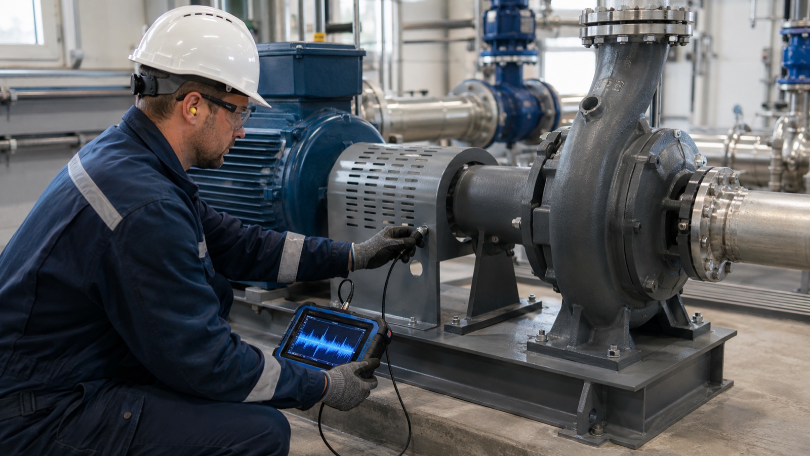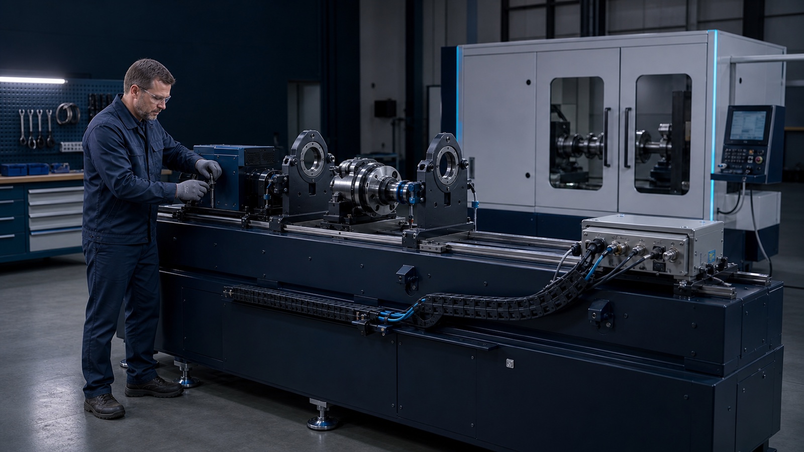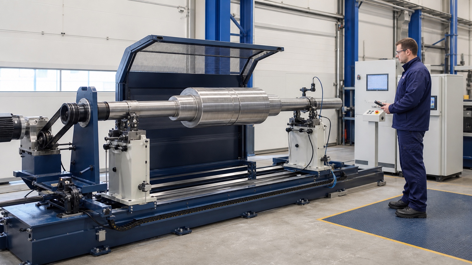
A balancing machine should not be selected by rotor weight or catalogue capacity alone. The decisive question is how the rotor, supports, sensors, drive, structure and measuring electronics behave as one dynamic system at balancing speed.
Short answer: a hard-bearing, below-resonance machine measures the reaction forces generated by unbalance while operating below the relevant natural frequency of the rotor-support system. A soft-bearing, above-resonance machine allows the supports to move and measures their vibration while operating above the suspension resonance. Hard-bearing systems are often selected for repeatable production, fast changeovers and permanent calibration. Soft-bearing systems are often selected for varied rotor work, high sensitivity at relatively low balancing speeds and flexible workshop projects. Neither principle is automatically more accurate; the correct choice is the one whose verified operating envelope, measuring chain and safety concept match the real rotor family.
This guide explains the physics, the practical differences and the data that should be included in a request for quotation before a balancing machine is approved.
The terms describe support dynamics, not the bearing hardware
“Soft-bearing” and “hard-bearing” do not primarily describe whether the rotor runs on a soft or hard rolling bearing. They describe the dynamic stiffness and response of the complete support system.
- In a hard-bearing or below-resonance machine, balancing speed remains below the relevant support-system resonance. The pedestals move very little and the measurement system evaluates reaction force.
- In a soft-bearing or above-resonance machine, balancing speed is above the natural frequency of the compliant suspension. The pendulum-like supports create measurable displacement, velocity or acceleration related to rotor unbalance.
For a balancing speed n in revolutions per minute, rotational frequency is:
f = n / 60
The design must keep the working range on the intended side of the relevant natural frequency fₙ and away from an unsafe or unstable resonance zone. The required separation cannot be selected from a universal percentage: it depends on damping, rotor mass and inertia, support stiffness, sensor range, drive forces, foundation response and the manufacturer’s validated design.
How unbalance becomes a measurable signal
Unbalance is commonly expressed as:
U = m × r
where m is an equivalent unbalance mass and r is its radius from the rotation axis. The rotating unbalance generates a centrifugal-force component proportional to the square of angular speed:
F = U × ω²
This relationship explains two important purchasing facts.
First, a force-measuring machine needs enough speed and a sufficiently sensitive force path to produce a reliable signal for the specified residual unbalance. Second, a compliant suspension can produce a useful motion signal at a lower speed, but that signal must remain linear, stable and correctly calibrated for the rotor and support configuration.
The machine does not “see” unbalance in isolation. It sees the response of an assembled measurement chain:
- rotor and tooling;
- journals, rollers, V-blocks or fixtures;
- soft or hard support modules;
- belt, end, universal-joint or self-drive system;
- vibration or force sensors;
- phase and speed reference;
- signal conditioning, analogue-to-digital conversion and synchronization;
- balancing software, correction logic and report generation;
- bed, foundation, guarding and nearby environmental influences.
If one element is changed, the usable range, calibration or uncertainty may also change.
Hard-bearing balancing machines: below resonance and force measuring
Hard-bearing machines use stiff pedestals and a defined force-transmission path. Because the supports have very small motion in the working range, the measuring system relates the detected reactions to unbalance using the rotor geometry, support positions and correction-plane data.
Where hard-bearing machines are strong
- Fast changeover and first-run measurement. Many modern hard-bearing systems use permanent calibration, so a new rotor setup can be measured without trial calibration runs after the required geometry is entered correctly.
- Repeatable production. A stable mechanical architecture is well suited to recurring rotor families, controlled recipes, takt-time targets and automatic correction.
- Large initial unbalance. Rigid supports can tolerate demanding starting conditions when the rotor, hold-downs, drive and sensor range have been engineered accordingly.
- Integration. Hard-bearing measuring stations are widely used with drilling, milling, welding, weight addition, marking, handling and line traceability.
- Defined force path. Force-measuring sensors and sealed transducers can be effective in industrial environments, provided installation and environmental requirements are met.
What must be checked
- Is the planned balancing speed high enough to generate a measurable force for the smallest required residual unbalance?
- Does the maximum initial unbalance remain within the support, sensor, drive and hold-down ranges?
- Is the bed or foundation stiff enough, and are nearby vibration sources controlled?
- Can the machine accept all journal diameters, bearing spans, overhung loads and correction-plane positions?
- Is permanent calibration valid across the entire approved configuration envelope, including tooling and support relocation?
Do not assume that every hard-bearing machine needs a massive special foundation. Some compact modern systems are designed for installation without one. Foundation, anchoring and environmental requirements must be confirmed for the specific machine and rotor range.
Soft-bearing balancing machines: above resonance and vibration measuring
Soft-bearing machines support the rotor on compliant, often pendulum-type suspensions. Balancing takes place above the suspension resonance, where unbalance produces a measurable support motion. Vibration transducers and the phase reference allow the instrument to calculate correction magnitude and angle.
Where soft-bearing machines are strong
- Sensitivity at relatively low speed. The compliant suspension can provide a strong displacement or vibration response without requiring the same force level as a rigid support.
- Wide rotor variety. Soft-bearing systems are often attractive for repair shops, prototypes, one-off rotors and projects with substantial changes in mass, span or geometry.
- Flexible installation. The suspension can provide useful isolation from some floor influences, although the supporting surface and environment still require engineering review.
- Large and heavy rotors. When high rotational speed would increase risk or drive power, an above-resonance architecture can be advantageous if the suspension and measurement range are designed for the load.
- Observable support motion. The measured movement can help diagnose setup problems, non-linearity, looseness or excessive initial unbalance.
What must be checked
- Which calibration method is required for each rotor family: trial weights, stored influence coefficients, electronic excitation or another validated procedure?
- How long does calibration and plane separation take during changeover?
- Is the intended balancing speed safely above suspension resonance for every mass and support configuration?
- Are suspension travel, sensor range and mechanical stops sufficient for the maximum initial unbalance?
- Do belt forces, aerodynamic forces, runout or fixture movement contaminate the 1× rotational signal?
It is inaccurate to say that every soft-bearing machine always requires the same trial-weight routine. Calibration method depends on the mechanical and measuring design. The supplier should state what is required for each approved rotor setup.
Soft-bearing versus hard-bearing: practical comparison
| Selection factor | Soft-bearing / above resonance | Hard-bearing / below resonance |
|---|---|---|
| Support behaviour | Compliant, measurable motion | Stiff, very small motion |
| Typical measurement path | Vibration, displacement, velocity or acceleration | Reaction force through rigid pedestal |
| Working relation to support resonance | Above the relevant suspension resonance | Below the relevant support resonance |
| Calibration | Often rotor- or setup-specific; method depends on system | Permanent calibration is common on modern systems |
| Changeover | Mechanically versatile; calibration work may add time | Often fast after geometry and support positions are entered |
| Low-speed sensitivity | Often a major advantage | Must be proven against force signal and sensor capability |
| Large initial unbalance | Limited by suspension travel, sensor range and stops | Often favourable, subject to support and hold-down design |
| Typical production fit | Repair, prototypes, varied or very large rotors | Repeated rotor families, serial production, automation |
| Installation | Can be comparatively flexible | Foundation needs are machine-specific, not universal |
| Accuracy | Depends on verified machine capability and process | Depends on verified machine capability and process |
This table is a selection guide, not a substitute for a dynamic model or supplier acceptance data.
Do not confuse machine type with rigid or flexible rotor behaviour
A soft-bearing machine does not automatically mean a flexible rotor, and a hard-bearing machine does not automatically mean a rigid rotor. These are separate classifications.
- Machine architecture describes the relationship between balancing speed and support-system resonance.
- Rotor behaviour describes whether the rotor deforms significantly within the speed range relevant to balancing and operation.
ISO 21940-11 addresses procedures and tolerances for rotors with rigid behaviour. ISO 21940-12 addresses rotors with flexible behaviour. A flexible rotor that changes modal shape with speed may require multi-speed or high-speed balancing, additional measurement planes, modal analysis, specialized tooling or balancing in an operating-like environment. Buying a soft-bearing low-speed machine does not by itself solve a flexible-rotor problem.
Which balancing machine should you choose?
Choose a soft-bearing architecture as the leading option when:
- the workshop handles many unrelated rotor types;
- balancing must be performed at the lowest practical speed;
- rotor mass, journal span or correction geometry changes substantially;
- the project includes very large rotors or difficult transport constraints;
- site flexibility matters more than the shortest possible changeover;
- the team can manage rotor-specific calibration and setup validation.
Choose a hard-bearing architecture as the leading option when:
- the same rotor families return repeatedly;
- first-run measurement and short changeover are critical;
- the line has a defined takt time and automated correction;
- recipes, traceability and statistical process control are required;
- large initial unbalance must be handled within a rigid mechanical path;
- the available balancing speed produces adequate force sensitivity.
Compare both architectures when:
- production combines repair work with recurring batches;
- the rotor range spans both light and heavy parts;
- low speed, fast changeover and automation are all important;
- future rotor families are not yet fixed;
- the procurement decision includes local bed fabrication or modular expansion.
In such cases, compare complete configurations against the same rotor matrix and acceptance test—not isolated support prices.
The rotor data required before requesting a quotation
A useful request for quotation should include at least the following.
Rotor and tooling
- minimum and maximum rotor mass;
- maximum diameter and overall length;
- journal diameters, widths, materials and surface condition;
- minimum and maximum bearing span;
- rotor centre-of-mass location and possible overhung loads;
- rotor drawing, 3D model and lifting points;
- own shaft, mandrel, fixture, complete assembly or bearing housing;
- anticipated maximum initial unbalance and its likely distribution.
Balancing duty
- rotor operating-speed range and intended balancing-speed range;
- rigid or flexible behaviour assessment;
- one-plane, two-plane or multi-plane correction;
- correction radii, planes, prohibited zones and permitted methods;
- required residual unbalance, balance-quality grade or product-specific limit;
- runout, key convention, assembly condition and any index-balancing requirement;
- expected batch size, product mix, cycle time and shifts per day.
Machine and site
- horizontal or vertical orientation;
- belt, end, universal-joint, self-drive or combined drive;
- available electrical power, floor capacity and foundation condition;
- guarding level, interlocks, extraction and safe loading method;
- temperature, dust, nearby machinery and background vibration;
- manual, assisted or automatic correction;
- data export, report format, user roles, recipe control and line interfaces;
- training, calibration, maintenance and spare-parts requirements.
“Rotor up to 1,000 kg” is not a complete specification. Two rotors of the same mass can require very different supports, drives, speeds, sensors and protection.
How to verify accuracy before acceptance
The most persuasive specification is not a screen resolution in g·mm; it is demonstrated performance on a defined machine configuration and proving rotor.
ISO 21940-21:2022 establishes requirements for evaluating hard-bearing and soft-bearing balancing machines supporting rotors with rigid behaviour at balancing speed, as well as rotors with shaft-elastic behaviour balanced by low-speed procedures. For procurement, agree the applicable standard edition and define the acceptance procedure in the contract.
Request evidence for:
- minimum achievable residual unbalance for the agreed rotor and setup;
- unbalance reduction performance over repeat runs;
- plane separation and cross-effect behaviour;
- repeatability after support movement and rotor changeover;
- calibration validity and traceability;
- speed and phase-reference stability;
- uncertainty contributors and environmental limits;
- results before shipment and after installation, where required.
The target balance quality for the rotor and the capability of the balancing machine are different questions. A machine may display a small number without reliably achieving it on the real part. Acceptance must connect the stated tolerance, rotor setup, correction method, measurement uncertainty and repeat test.
Safety is part of the selection, not an accessory
Lower balancing speed can reduce kinetic energy, windage and some rotor-related risks, but low speed is not a complete safety strategy. The safety concept must consider maximum credible speed, maximum initial unbalance, rotor retention, drive failure, detached components, tooling, correction operations, loading and human access.
ISO 21940-23 covers enclosures and other protective measures for the measuring station of centrifugal balancing machines. The required protection must be selected for the real rotor and operating conditions. Guards, hold-downs, end-thrust restraints, interlocks, safe braking and risk assessment belong in the machine scope from the start.
Seven costly selection mistakes
- Choosing by maximum rotor mass only. Mass says little about journal load, inertia, span, drive torque, correction access or residual-unbalance sensitivity.
- Assuming hard-bearing means accurate and soft-bearing means approximate. Both principles can perform precision work when properly designed, calibrated and verified.
- Using catalogue speed as the balancing speed. The usable speed depends on resonance separation, signal quality, rotor safety, drive capacity and aerodynamic forces.
- Confusing a flexible suspension with a flexible rotor. Rotor modal behaviour requires its own engineering assessment.
- Buying supports, sensors and software independently. Their ranges, signal conditioning, phase synchronization and calibration must be compatible.
- Ignoring the correction process. Measuring unbalance has little value if drilling, milling, welding or weight addition cannot reach the required planes safely and repeatably.
- Accepting a generic demonstration. Test the quoted configuration against a representative rotor matrix and documented acceptance criteria.
A practical decision rule
If your priority is variety, heavy rotors and useful sensitivity at low balancing speed, begin the engineering comparison with a soft-bearing system. If your priority is repeatable production, rapid changeover and automation, begin with a hard-bearing system. Then challenge that first choice with the real rotor matrix, speed-resonance map, calibration procedure, correction process, safety case and acceptance test.
The correct answer may also be a dedicated vertical machine, a driveshaft machine with multiple supports, a high-speed facility for flexible rotors, or two different cells. “Universal” should mean a documented operating envelope—not a promise that one machine can balance every rotor.
Frequently asked questions
Which type is more accurate: soft-bearing or hard-bearing?
Neither type is inherently more accurate. Accuracy depends on the complete machine, rotor setup, calibration, speed, sensor range, plane separation, environmental conditions and acceptance method. Compare demonstrated residual-unbalance capability and repeatability for your rotor family.
Does a soft-bearing machine always need trial weights?
No. Many soft-bearing workflows use rotor-specific calibration or trial weights, but some systems support stored coefficients, electronic excitation or other calibration methods. The supplier should define the exact procedure and when it must be repeated.
Can a hard-bearing machine balance at low speed?
Yes, if the unbalance force at that speed is large enough for the force-measuring chain to achieve the required uncertainty and residual-unbalance target. This must be demonstrated, not assumed.
Is a G 6.3 balance-quality grade enough to select a machine?
No. A quality grade must be connected to rotor mass and service speed to derive the permissible residual unbalance, and the project must still define correction planes, setup, measurement uncertainty, safety and production rate.
Can one balancing machine handle both one-plane and two-plane balancing?
Many dynamic machines can calculate static and couple components and balance in two planes, but the rotor geometry, correction-plane separation and tooling must support reliable plane separation. Thin disc-shaped rotors may only require one plane; long rotors commonly require two or more.
Is soft-bearing the same as high-speed balancing?
No. “Soft-bearing” describes support dynamics. High-speed balancing concerns the rotor’s behaviour and correction across a higher speed range, often involving flexible-rotor modes and specialized containment.
What should be tested at factory acceptance?
The contract should define the representative rotor or proving rotor, setup, speed, calibration state, allowable residual unbalance, repeatability, unbalance reduction, reporting and safety functions. Site acceptance may need to repeat relevant checks after installation.
Configure the measurement chain as one system
Every part has a defined role: bed and rails, soft or hard supports, drive module, sensor set, phase reference, measurement electronics, balancing software, guarding, correction equipment and line interfaces. Interfaces, ranges, wiring, software licences, drawings and calibration records should travel with the project.
Use JAZARION to compare balancing-machine architectures, create a preliminary modular configuration or submit your rotor package for engineering review. Price, performance, delivery, compliance and the final machine architecture are confirmed only after the rotor data, operating conditions and acceptance requirements are reviewed.
Standards and technical sources
- ISO 21940-21:2022 — Description and evaluation of balancing machines
- ISO 21940-11:2016 — Procedures and tolerances for rotors with rigid behaviour
- ISO 21940-12:2016 — Procedures and tolerances for rotors with flexible behaviour
- ISO 21940-23:2012 — Enclosures and other protective measures
- Schenck RoTec HM hard-bearing balancing machines — permanent calibration and modular applications
- Hofmann horizontal force-measuring balancing machines
- IRD Balancing — explanation of soft-bearing and hard-bearing machine response
This article provides engineering guidance. It does not replace the controlled editions of applicable standards, a rotor-dynamics study, machine risk assessment, contractual acceptance criteria or approval by the responsible engineer.