Vibration diagnostics turns the dynamic response of an operating machine into evidence for maintenance decisions. A properly designed programme can reveal developing mechanical problems, track deterioration, support planned repairs and verify whether an intervention improved the machine. It is not simply “checking a vibration number”, and a portable analyser does not automatically produce a reliable diagnosis.
Short answer: routine vibration data can be collected by a trained and authorised technician following a controlled route. Interpretation, fault diagnosis and recommendations must be made by personnel whose training, experience and assessed competence match the machine and the consequence of the decision. ISO 18436-2 specifies training, relevant experience and examination requirements for vibration-analysis personnel and uses a four-category classification programme. Local law, the asset owner’s safety rules, the equipment manufacturer and the contract can impose additional requirements.
What vibration diagnostics is
Every rotating or reciprocating machine produces vibration. The useful question is not whether vibration exists, but whether its magnitude, frequency content, phase, waveform and change over time are consistent with the machine’s design and operating state.
Vibration condition monitoring is the repeatable collection and comparison of data. Vibration diagnosis goes further: it connects measured patterns with plausible fault mechanisms, checks competing explanations and recommends the next action with an explicit level of confidence.
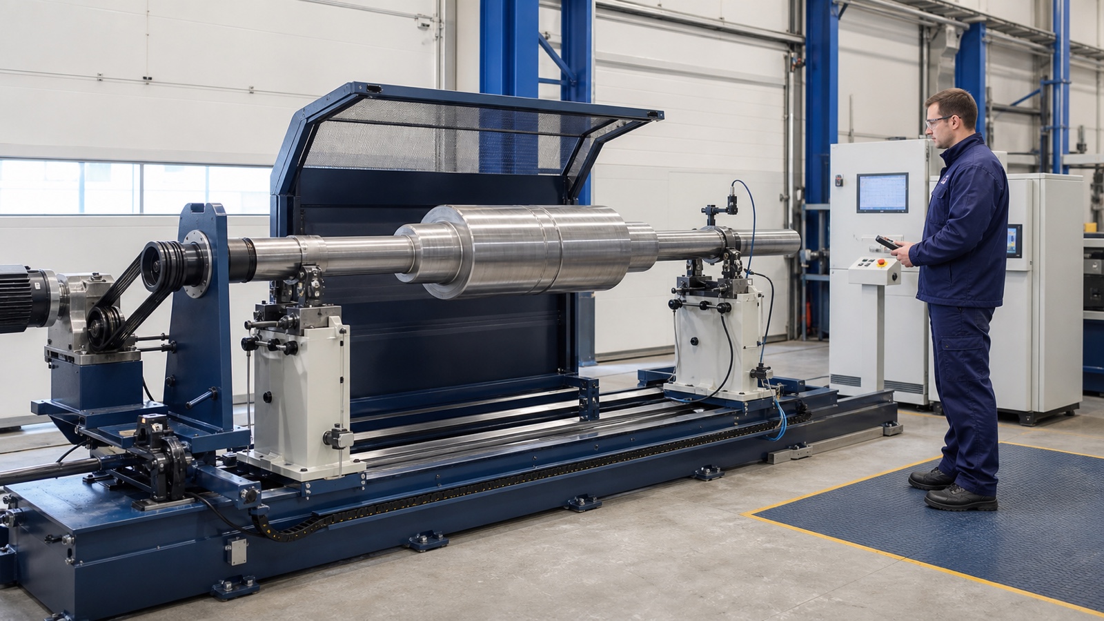
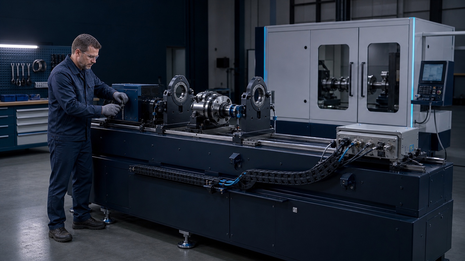
The method is commonly applied to motors, pumps, fans, blowers, compressors, gearboxes, turbines, generators, spindles, rolls and other machine trains. It can be periodic, using route-based measurements, or continuous, using permanently installed sensors and a monitoring system.
Why plants use vibration diagnostics
A useful programme answers operational questions rather than producing graphs for their own sake.
- Detect change early. A trend can show deterioration before noise, heat or product-quality loss becomes obvious.
- Plan maintenance. The team can investigate and prepare parts, labour and downtime instead of reacting to an unplanned stop.
- Distinguish possible fault families. Frequency, phase and waveform evidence can help separate unbalance, misalignment, looseness, resonance, bearing or gear phenomena and process excitation.
- Prioritise risk. Condition evidence can be combined with asset criticality, safety, production and spare-part exposure.
- Verify work. Before-and-after measurements can show whether alignment, balancing, bearing replacement, foundation work or another intervention changed the response as intended.
- Improve asset knowledge. A stable history links vibration to load, speed, process state, maintenance events and failure findings.
The economic value does not come from the sensor alone. It comes from finding a consequential problem early enough to choose a better action.
What can vibration analysis reveal?
Vibration evidence may support investigation of:
- rotor unbalance and eccentricity;
- shaft or coupling misalignment;
- mechanical looseness, soft foot and structural weakness;
- resonance and inadequate separation from excitation frequencies;
- rolling-element bearing damage or lubrication-related distress;
- gear mesh problems, wear or tooth damage;
- belt, blade, vane and aerodynamic or hydraulic excitation;
- rub, bent shaft, cracked or loose components;
- selected electrical and electromagnetic phenomena in motors;
- process instability, cavitation-like behaviour or flow-induced excitation.
These are diagnostic hypotheses, not automatic conclusions. Similar spectral features can have different causes, and more than one fault can be present. A credible diagnosis combines vibration with operating data, inspection history and, when appropriate, alignment, temperature, oil, electrical, ultrasonic, process or dimensional evidence.
Measurement is not the same as diagnosis
An overall vibration value can be useful for screening and trending, but it compresses a complex signal into one number. Two machines can show a similar overall level while having very different spectra and risk.
Depending on the machine and objective, the measurement set may include:
| Evidence | What it contributes | Common limitation |
|---|---|---|
| Overall velocity, often RMS | Broad severity and trend view for many industrial machines | Can hide narrow-band or impact phenomena |
| Acceleration and high-frequency content | Sensitivity to impacts and selected bearing or gear effects | Strongly affected by mounting, bandwidth and filtering |
| Displacement or relative shaft vibration | Shaft motion and low-frequency behaviour where applicable | Requires the correct sensor geometry and machine-specific criteria |
| Frequency spectrum | Separates components by frequency and links them to running speed or machine elements | Peaks are not diagnoses without context |
| Time waveform | Shows impacts, modulation, clipping and non-stationary behaviour | Needs suitable sample length and scale |
| Envelope or demodulation analysis | Can reveal repetitive high-frequency impacts | Setup and interpretation are application-dependent |
| Phase and speed reference | Helps with unbalance, alignment, resonance and operating-deflection questions | Requires stable reference and consistent conventions |
| Orbit or shaft-centreline plots | Useful for selected fluid-film-bearing machines | Not meaningful without suitable orthogonal probes and expertise |
ISO 13373-1 addresses measurement and data-collection procedures, including transducer selection, location, attachment and machine operating conditions. ISO 13373-2 addresses processing, analysis and presentation. ISO 13373-3 provides a structured approach to vibration diagnosis. The applicable machine-specific standard and manufacturer criteria must still be selected.
Why one universal vibration limit is unsafe
There is no single alarm value that is correct for every motor, pump, gearbox, turbine and spindle. Evaluation depends on machine type, power, speed, support, measurement location and direction, operating state, sensor quantity, frequency range and whether the purpose is acceptance or in-service monitoring.
ISO 20816-1 provides general conditions for measuring and evaluating machine vibration and considers both magnitude and change. Other parts of ISO 20816 cover defined machine classes. ISO 20816-3:2022, for example, applies to specified coupled industrial machines above 15 kW and within a stated speed range; it also warns that broad-band values do not replace assessment of specific frequency components.
A sound alarm strategy therefore combines:
- the correct machine-specific standard or contractual acceptance criterion;
- manufacturer limits and known design constraints;
- a verified baseline for the machine and measurement point;
- rate of change and repeatability;
- operating state, load, speed and process conditions;
- fault-specific analysis and consequence of failure.
Who can perform vibration diagnostics?
The answer depends on what “perform” means.
Route measurement and basic screening
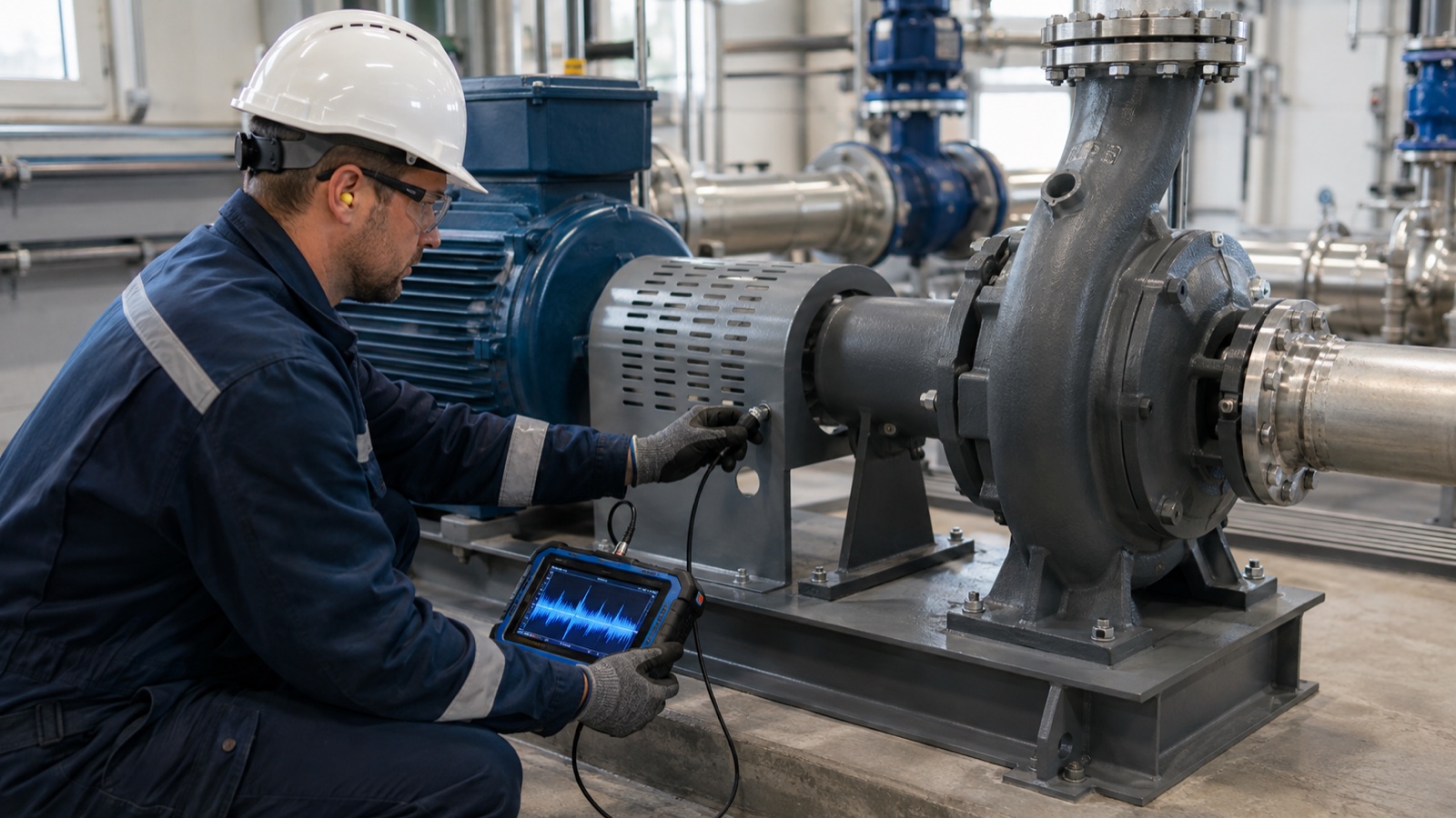
A trained technician may collect repeatable route data and identify that a value or trend has crossed an approved rule. The person needs authorised access, machine-safety training, correct sensor placement, knowledge of the route and operating state, and the ability to recognise invalid data. This role should not be expected to issue a complex diagnosis outside its defined procedure.
Analysis and fault diagnosis
A vibration analyst or reliability engineer should interpret spectra, waveforms, phase and trends, connect them to machine kinematics, consider alternative causes and define confirmatory checks. The required competence rises with machine complexity and the consequence of a wrong decision.
Programme design and high-consequence decisions
Senior specialists should define the monitoring strategy, measurement database, alarm philosophy, sensor selection, acceptance criteria, diagnostic escalation and quality controls. Turbomachinery, flexible rotors, fluid-film bearings, variable-speed systems, reciprocating machines and safety-critical assets may require specialised machine knowledge in addition to general vibration competence.
ISO 18436-2:2014 is the central international reference for qualification and assessment of vibration-analysis personnel. It requires training, relevant experience and examination and defines four categories. ISO 18436-1:2021 sets sector-specific requirements for certification bodies and the certification process. A certificate is useful evidence of assessed competence, but it does not replace site authorisation, machine-specific experience, safe-work rules or accountability for the maintenance decision.
For contracted work, verify the individual’s certificate scope and validity, relevant machine experience, reporting method, equipment calibration status and professional liability arrangements where applicable. Do not accept a company logo or course-attendance paper as proof that the person is competent for every diagnostic task.
A controlled vibration-diagnostic workflow
1. Define the decision
State whether the objective is baseline commissioning, periodic monitoring, fault investigation, post-repair verification, acceptance testing or protection. Each objective needs different data and authority.
2. Establish safety and access
Measurements near operating machinery require a documented safe method. Keep guards and interlocks effective, control loose clothing and cables, respect exclusion zones, and never reach across rotating parts. If a safe measurement point is unavailable, redesign the access or install a permanent sensor; do not improvise around a hazard.
3. Record the machine and operating state
Capture asset identity, driver and driven equipment, rated and actual speed, load, flow or pressure, temperature, control mode, lubrication state and recent maintenance. Variable-speed equipment requires speed-linked data.
4. Define repeatable measurement points
Specify point, direction, sensor type, mounting method, units, bandwidth, sampling and route order. A reading taken on a thin guard cannot be compared with one taken on a bearing housing.
5. Build a valid baseline
Commissioning data or a known-good condition is more valuable than an arbitrary first reading. Record configuration changes so that a new motor, foundation, coupling or sensor does not silently break the trend.
6. Analyse and corroborate
Check data quality before interpreting it. Compare overall values, spectra, waveforms, phase and process variables. Test the most plausible hypotheses with additional measurements or inspection.
7. Recommend an action with confidence and urgency
Separate observation, diagnosis, evidence, uncertainty, risk and recommendation. “Bearing fault” is not an action plan. A useful report states what was observed, the likely mechanism, confidence, consequence, required confirmation, operating restriction if any, and the next review date.
8. Close the loop
After maintenance, repeat the relevant measurements under comparable conditions. Record the physical finding. This is how the programme learns whether its diagnoses and thresholds are effective.
What a professional report should contain
- asset and measurement-point identification;
- date, operating state, speed and load;
- sensor, mounting, analyser and relevant settings;
- calibration or verification status;
- values with units and frequency range;
- trend, spectrum and waveform where relevant;
- observations separated from diagnostic conclusions;
- probable fault mechanism and alternative explanations;
- confidence, severity and consequence basis;
- recommended confirmation and maintenance action;
- urgency, restrictions and responsible owner;
- reference criteria and next measurement date.
Common mistakes
- Diagnosing from one overall number. It can screen condition but rarely identifies a fault by itself.
- Comparing unlike operating states. Speed, load, temperature and process changes can dominate the signal.
- Moving the measurement point. Small changes in location, direction or attachment can break the trend.
- Using a magnetic base on an unsuitable surface. Poor contact and rocking alter high-frequency response.
- Calling every 1× peak unbalance. Misalignment, eccentricity, resonance and process forces can also appear at running speed.
- Applying a generic alarm to every asset. Machine-specific criteria and change are essential.
- Ignoring repair feedback. Without confirming the physical finding and post-work response, diagnostic quality cannot improve.
- Treating software output as an authorised decision. Automated labels can assist screening, but responsibility remains with competent personnel and the asset owner’s process.
Frequently asked questions
Can a mechanic take vibration measurements?
Yes, if the mechanic is trained, authorised, follows a controlled procedure and works safely. Complex interpretation and maintenance recommendations should be escalated to a person with the required vibration-analysis and machine-specific competence.
Is certification legally mandatory?
There is no single worldwide rule. Requirements depend on jurisdiction, sector, contract, asset owner and consequence. ISO 18436 certification is internationally recognised evidence of competence, but local legal and site requirements must be checked for the actual project.
Can a smartphone diagnose a machine?
A phone may support a limited demonstration or rough screening, but sensor response, mounting, sampling, bandwidth, calibration and repeatability are usually not controlled well enough for consequential industrial decisions. Use fit-for-purpose instrumentation and a documented method.
Does high vibration always mean unbalance?
No. Unbalance is one possibility. Misalignment, looseness, resonance, bearing or gear effects, hydraulic or aerodynamic excitation, electrical phenomena and external vibration can produce high levels.
Can vibration analysis predict the exact failure date?
Usually not by itself. It can detect and trend deterioration, but remaining-life estimates need a validated degradation model, stable operating context and uncertainty. Report a decision window and confidence instead of a false exact date.
Is vibration diagnostics the same as balancing?
No. Diagnostics identifies and assesses machine-condition mechanisms. Balancing changes mass distribution to reduce rotor unbalance. A diagnosis should justify balancing before correction weights are added or removed.
Prepare a vibration-diagnostic scope before ordering work
For a useful technical request, provide the machine train, drawings or nameplate data, speeds and loads, symptoms, event history, criticality, existing measurements, available access, required decision and reporting format. State whether the need is a one-time investigation, route programme, permanent monitoring, acceptance test or post-repair verification.
Use JAZARION to review balancing and measurement-system options, explore industrial machine capabilities or submit a vibration-diagnostic project scope for engineering review. Supplier, personnel, method, price, timing and final acceptance criteria are confirmed only after the real asset, operating conditions, safety requirements and required decision are reviewed.
Standards and official sources
- ISO 17359:2018 — General guidelines for condition-monitoring programmes
- ISO 13373-1:2002 — Vibration measurement and data-collection procedures
- ISO 13373-2:2016 — Processing, analysis and presentation of vibration data
- ISO 13373-3:2015 — Guidelines for vibration diagnosis
- ISO 18436-2:2014 — Qualification and assessment of vibration-analysis personnel
- ISO 18436-1:2021 — Requirements for certification bodies and certification process
- ISO 20816-1:2016 — General guidelines for measurement and evaluation of machine vibration
- ISO 20816-3:2022 — Evaluation for specified coupled industrial machinery
- ISO 13379-1:2025 — General guidance on data interpretation and diagnostic approaches
- ISO 12100:2010 — Machinery risk assessment and risk reduction
Source status and editions were checked on 4 September 2026. ISO 18436-2:2014 and ISO 20816-1:2016 remained published while revisions were under development; project specifications should identify the required edition rather than silently assuming “the latest”.